external: index
internal: preamble problem atlas poly-view wire-frame mystery more-views conclusion Cullam poly-view 2 terrafit ... end
2009-11-17: TerraGear (GIT) revisited. To try to solve some scenery generation errors! But are they scenery 'generation', or scenery 'rendering' problems?
It is for sure that once the complexity of the scenery passes a certain level, these problems become apparent in the rendered scene, but a study of the internals of the binary terragear file (BTG) show they appear to be 'normal'. Very complex, but normal! SO, WHAT IS THE PROBLEM?
As is often said, some pictures are worth a thousand words... click the image to see in full 800x600...
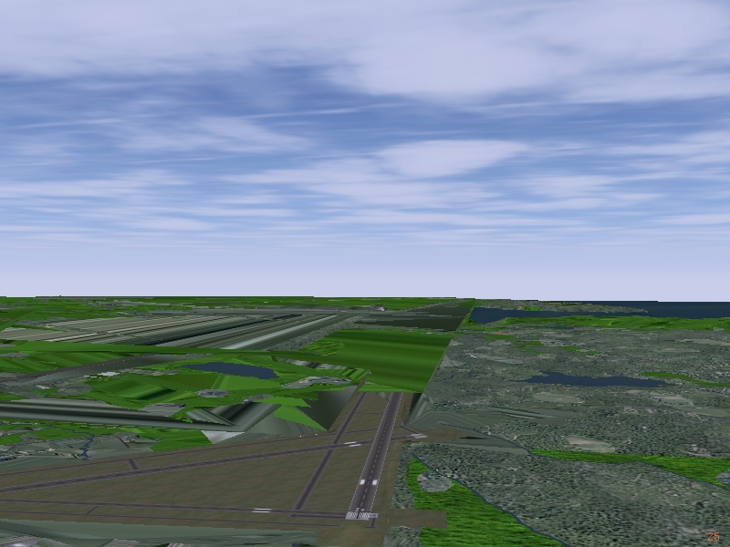
| location: --lat=47.6280278 --lon=-52.715194 --heading=260 --altitude=2500 (CYYT) |
|
|
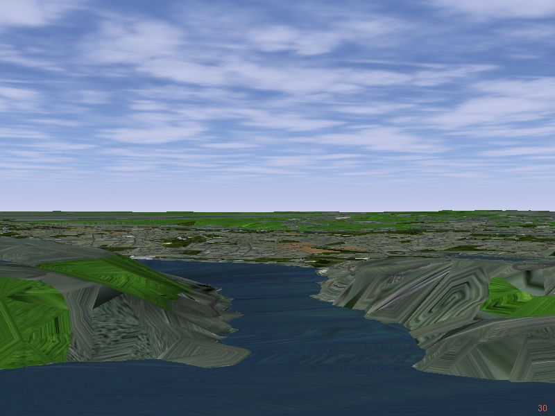
| location: --lat=47.5618611 --lon=-52.667167 --heading=288 --altitude=900 (St. John's) |
|
|
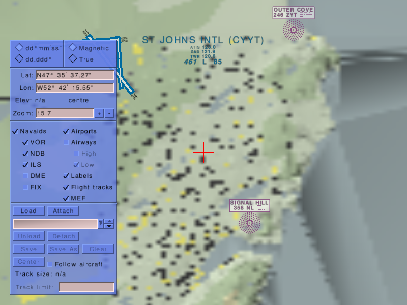
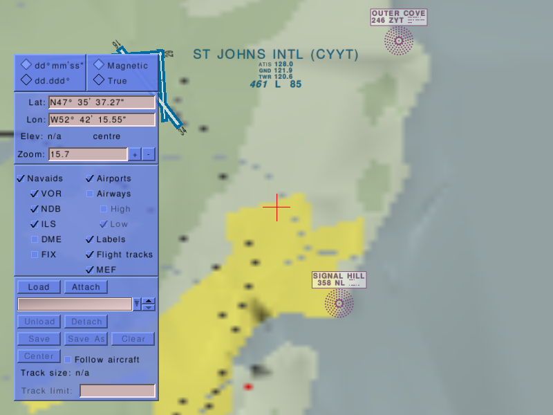
Some views using Atlas. This is after the Map utility has converted the BTG files to PNG images. NOT sure if this shows the aberration problem, or not, but they certainly 'look' different!
| Using hi-res CanVec data - map: CVScene3 to CVpng | Standard Scenery 1.0.1 -. 101png |
|
|
| atlas: --fg-root=..\..\..\data --atlas=[CVpng|101png] --lat=47.59368588 --lon=-52.70432006 --zoom=15.7 | |
What is particularly disturbing is the heavy shading, the 'waves', in the ocean! It looks like tsunami waves hitting St. John's ;=)) I think these should _NOT_ be there, and suggests this 2089569.btg.gz, generated using the TG tools, and the CanVec data is somehow 'faulty'!
2009-11-27: I have a rather crude (WIN32 only) poly-view application I use to view TG polygon files, so I modified it to load and also display BTG files. That is it does essentially what FlightGear does, except it does not represent elevation - it is a SIMPLE 2D view of the tris, fans, etc in the BTG file. Here is a comparison of some views just SE of CYYT, NFL, using first the CanVec data, just for tile 2089569, and then standard 1.0.0 TG scenery. Clicking on each image will load the full 600x600 image in a new window :-
| CanVec data | Scenery 1.0.1 |
|---|---|
|

|
|

|

|
|
|
|
The left CanVec BTG does seem VERY WELL FORMED, and this does tend to indicate the problems in the top displays is in the final FG tile display system, and not during the construction phase ;=(( These views are around a center lon, lat of -52.731165,47.603897, except the first, which is centered on the CYYT airport, where the CanVec data is only in the lower right quadrant.
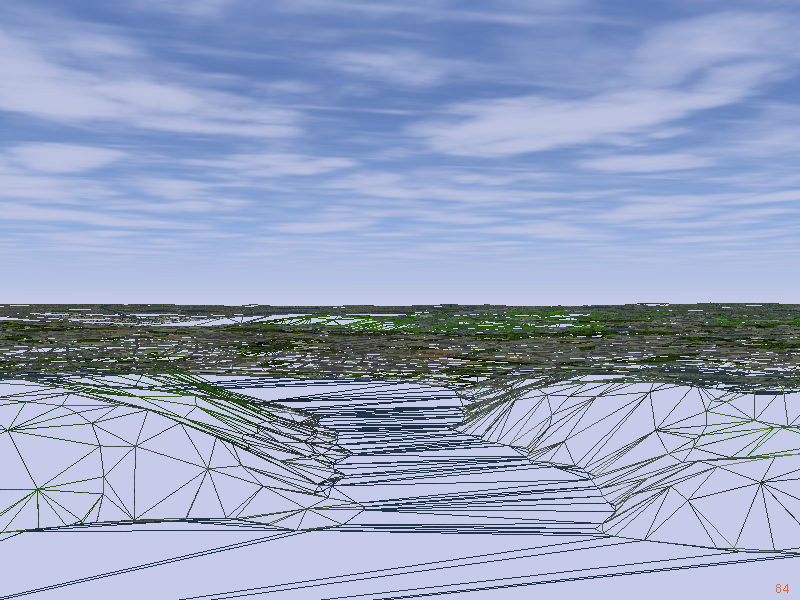
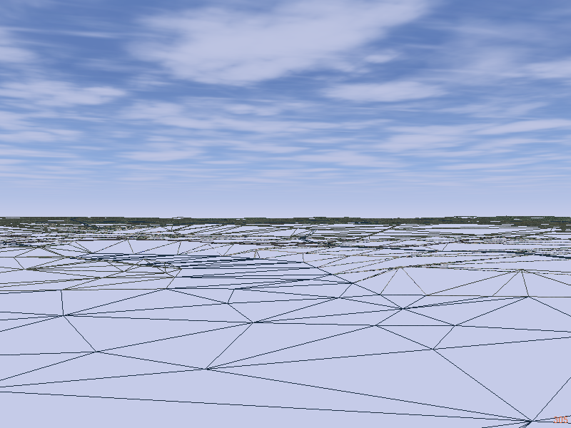
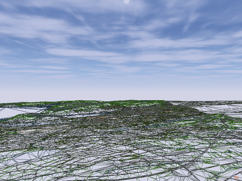
And some comparative view using FG in wire-frame rendering mode - that is using --enable-wireframe on the command line :-
| CanVec data | Scenery 1.0.1 |
|---|---|
|
|
|
|
These show the massive change in the complexity of the scenery.
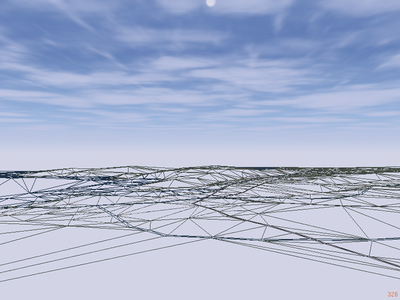
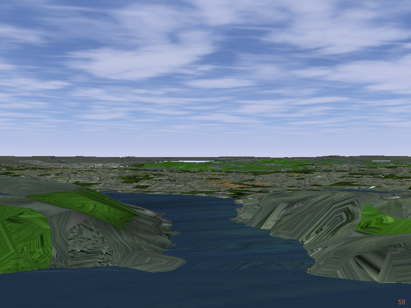
That is there is a MASSIVE increase in polygons to be drawn, but that still does not clearly explain why this happens! The front left cliff looks quite normal in the wire-frame image, but when loaded and displayed in FlightGear shows 'bands' that should not be there. Likewise for the right side cliffs, and other parts :-
| Why does the seemingly good wire-frame on the left, become this banded display when rendered in FG on the right? | |
|
|
|
This is the mystery still to be solved!
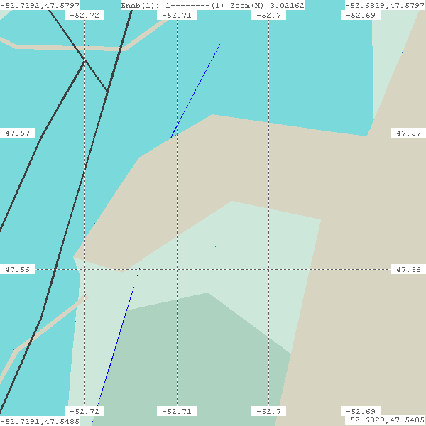
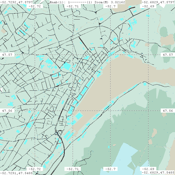
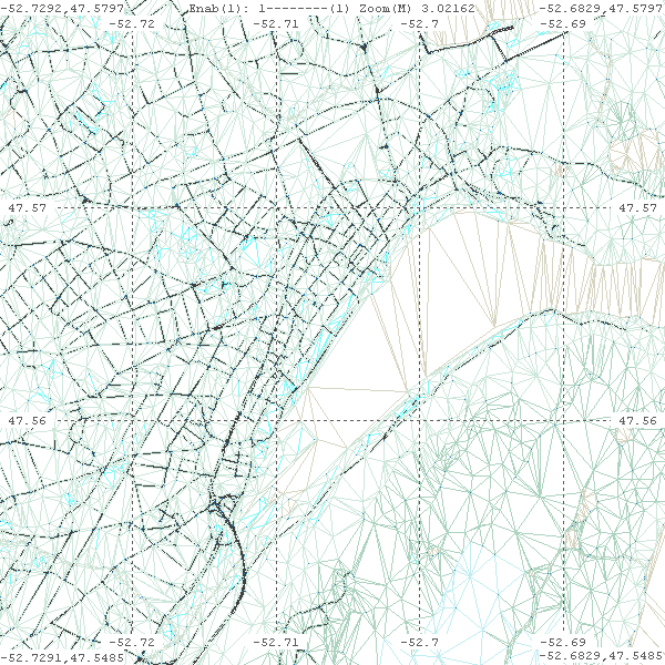
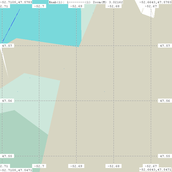
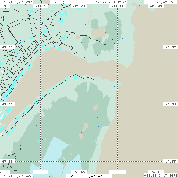
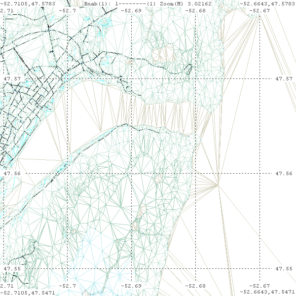
And to try to look closer... These are 2 sets of 4 images, using my poly-view. The first 4 are centered over the St. John's harbor, while the second 4 concentrate more on the headlands. The first 2 of each 4 are using 1.0.1 data, filled, and wire-frame respectively, and the second 2 of the 4 are using the CanVec data, again filled and wire-frame respectively. Of course, clicking each image will open it in a new window showing better detail...
Although the SAME 'paint' center, and scale is used for each set of 4 - the first using --center-lon-lat=-52.706041,47.564130, over St. John's, the second set of 4 using --center-lon-lat=-52.687398,47.562674, over SJ headlands, the CanVec data appears shifted right (East) about 0.01 degrees, but they look about the same North/South! Not sure what this signifies...
| [1] Set of 4 --center-lon-lat=-52.706041,47.564130 | |
|

|
|
|
| [2] Set of 4 --center-lon-lat=-52.687398,47.562674 | |
|

|
|
|
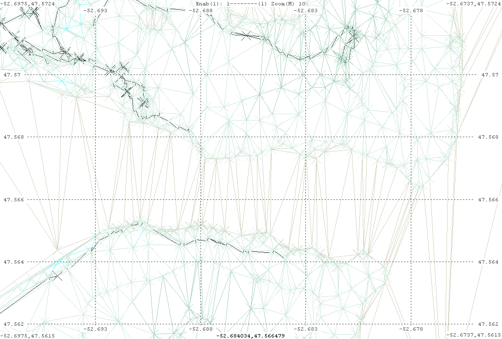
The last image, slightly zoomed, is also available in a higher resolution - pvCVSJ2wf2.png - full screen, and with another feature enabled, and that is painting an 'X' for each point. It may show more...
These poly-view images tend to reinforce the idea that the BTG file contents are OK, and the problems occurs during FG rendering, but it still remains a mystery...
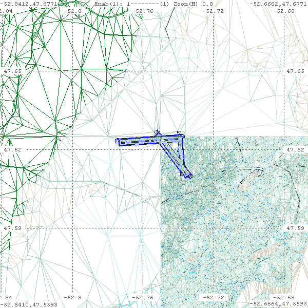
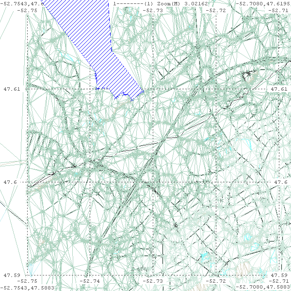
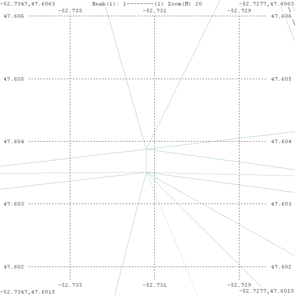
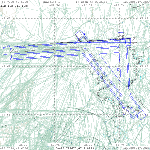
2009-11-30: Cullam has generated some real beauties that show this problem in exquisite detail ;=)) He 'pushed' the terrafit tool first using 3 m error, then 0.1 m error. Around the CYYT airport there are 4 tiles - 2089576, 2089577, 2089568 and 2089569. While three of these tiles look well formed, 2089568 is a MESS. There seems no semblance of tris, tri-fans, etc... poly-view thus paints and joins the wsg84 nodes from the BTG file, and these images show just a big crisscross of lines! Click each image to open the full size 600x600 png image in a new window...
| [1] 3 m error | ||
|
|
|
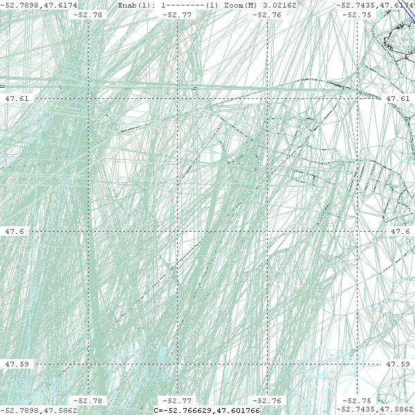
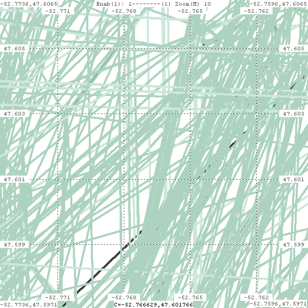
| [2] 0.1 m error | ||

|
|
|
This seems to indicate, at least for tile 2089568, that the tile construction went real wrong! And naturally FG rendering of this tile will likewise be a mess. So perhaps this indicates there are in fact two, perhaps related, but 2 separate problems. One is in the tile construction with TG tools, and the other is in FG rendering when it comes to display these tiles - UGH!
An ongoing saga!
2009-12-07: I coached my WIN32 poly-view to directly load a BTG file, and display the contents. And as indicated above three seem to be two separate problems.
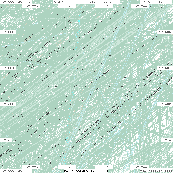
Problem 1: These two images were using 2089569.btg.gz - The first from Scenery 1.0.1, and the second using CanVec data - chalk and cheese ;=)) Click the image to view in full 1024 x 692 format.
|
|
While the 2nd hi-res BTG looks very well formed, it does not display correctly in FG. There are strange contour like patterns generated, which should not be there, as shown in the 2nd top image. This seems to indicate that while the BTG is well formed, there is a problem in FG 'rendering' of this scene tile.
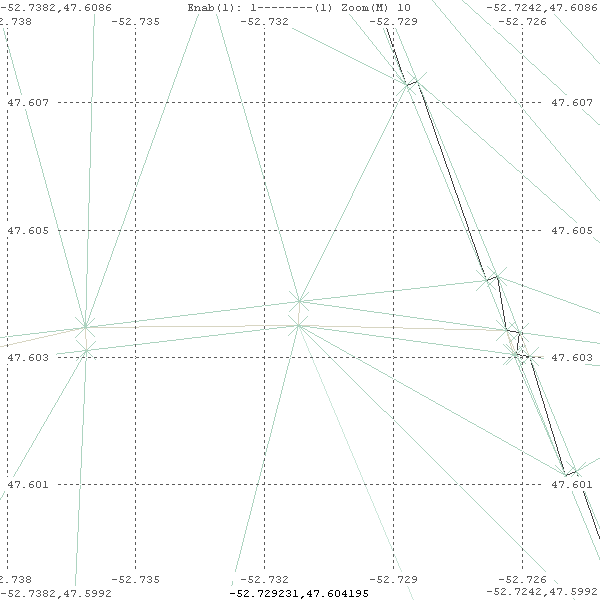
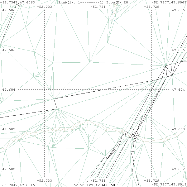
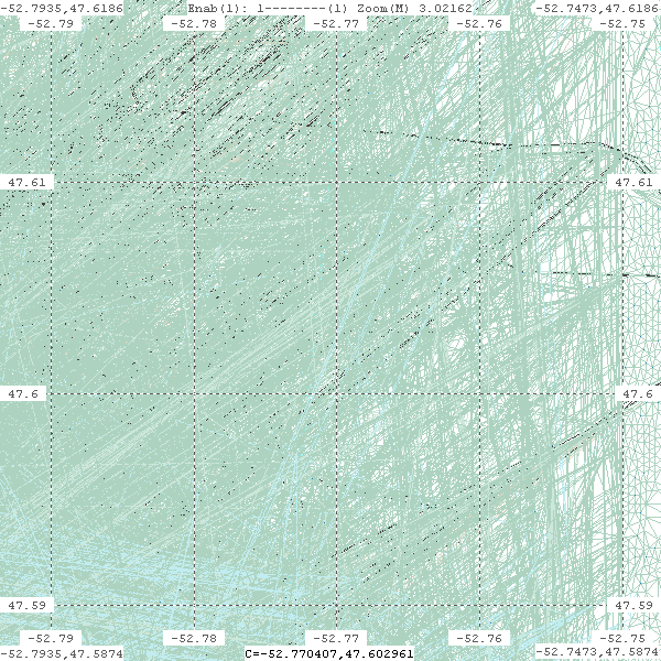
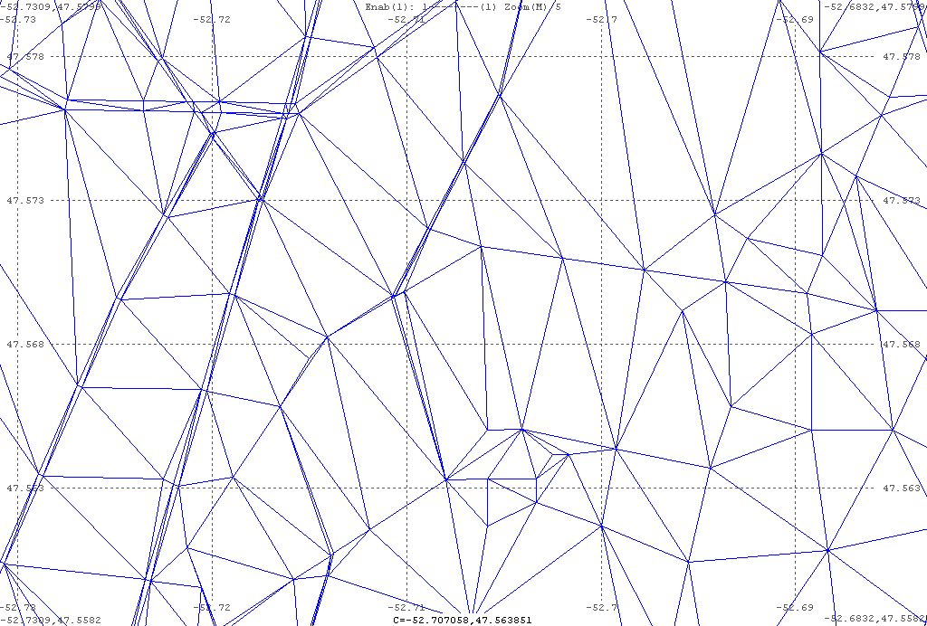
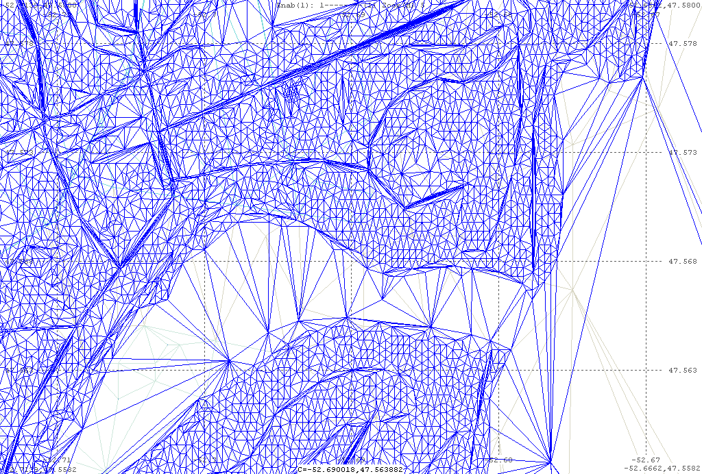
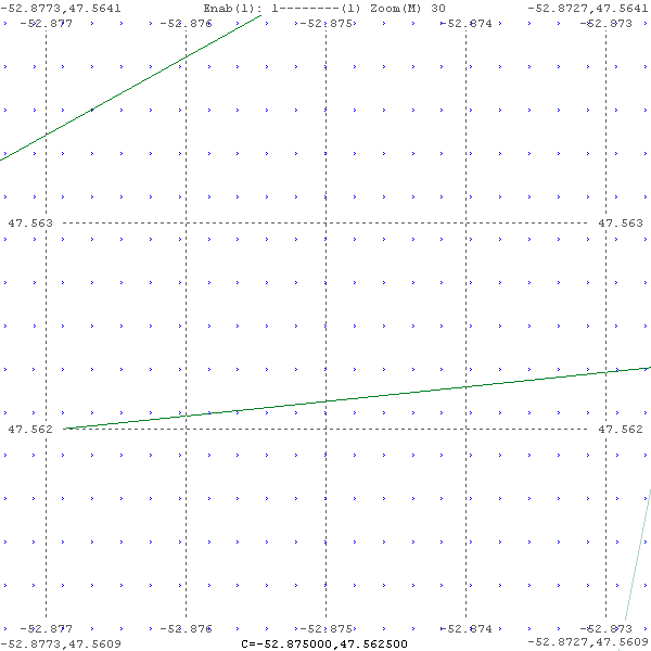
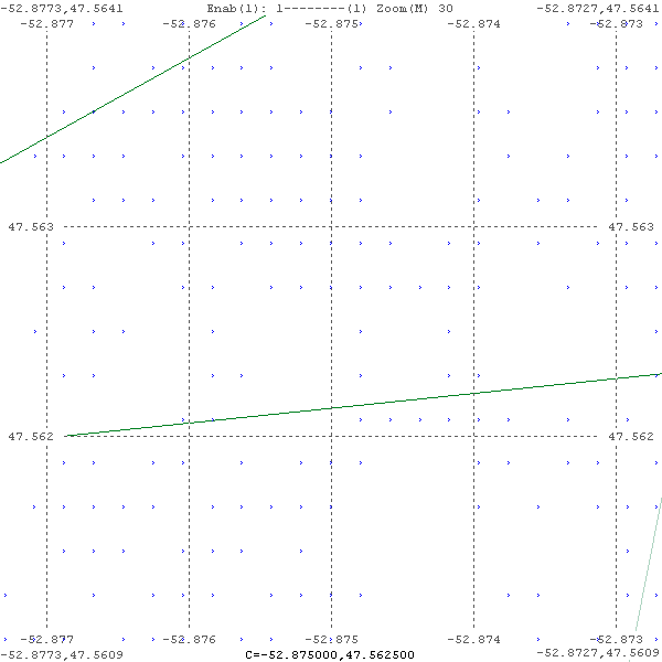
Problem 2: The following images are using tile 2089568.btg.gz. The first is normal scenery 1.0.1. The second is using the hi-res CanVec data. And the 3rd is the 2nd zoomed some 60 times. All that can be seen is a CRAZY MESS OF LINES! Click image to see full 600x600 in a new window.
|
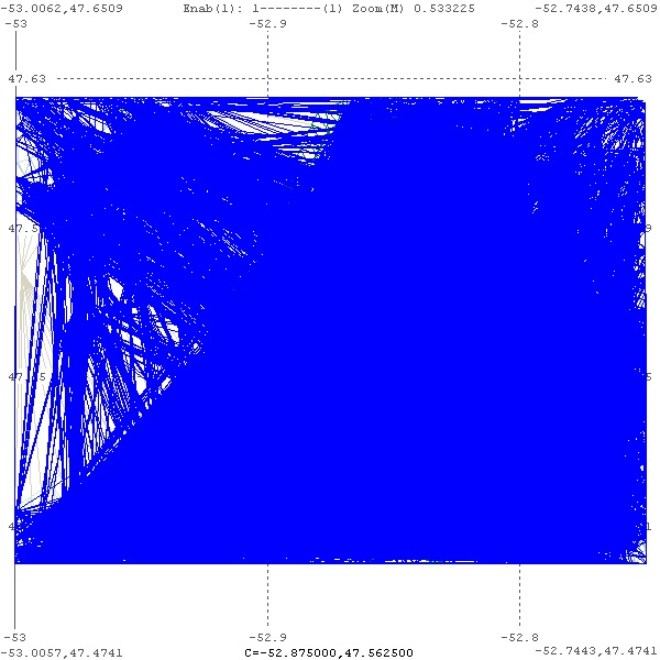
|
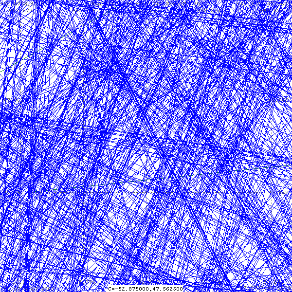
|
This indicates an error in fgfs-construct. It has completely failed, and obviously the rendering by FG will also be very faulty.
Two problems to solve!
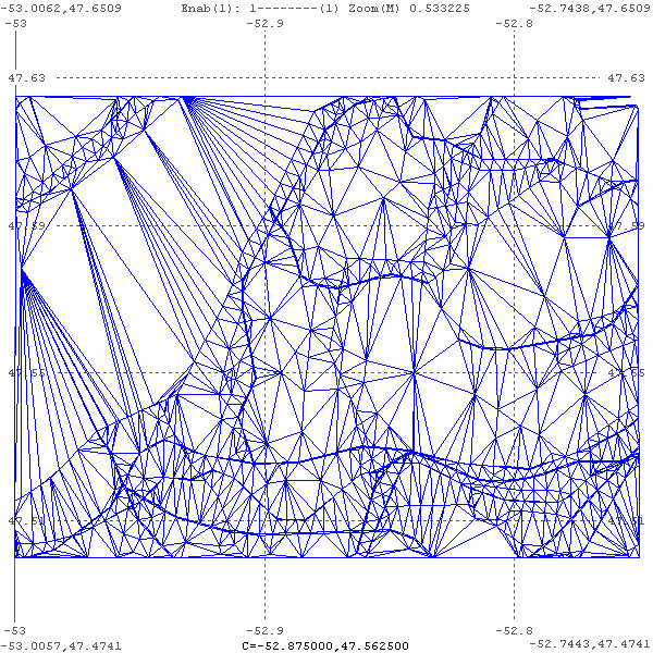
2009-12-09: While in the mood of modification, I further modified my poly-view to load 2089568.arr.gz (left), and 2089568.fit.gz (right). However it is only a 2D rendition of the points.
|
|
This was done to try to 'understand' the Terrafit process, which takes an 'array' file, and generates a 'fit' file.
EOP - fgfs-050b.htm